Thanks to the Internet of Things and electronics, medical care is becoming increasingly personalised and continuous. Today, patients who need to be closely monitored and continuously medicated can be treated with the help of wearable medical syringes. Medical staff can monitor and adjust the amount and flow rate of medication via wireless communication. The smaller syringe size accommodates the patient’s daily activities and frees the patient from the burden or limitations of a wired device (Figure 1).
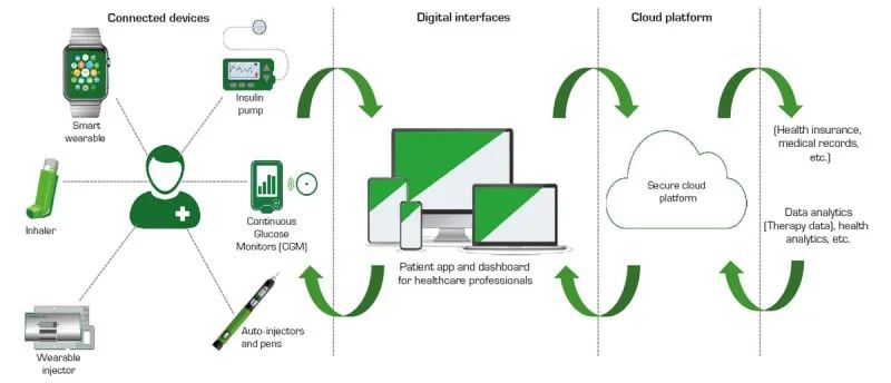
Figure 1: Connected drug delivery systems are disrupting the way patients take their medication
Designers must develop products that operate reliably at any time. The production needs to meet the requirements of high efficiency as much as possible to maximize the battery’s endurance. Given the limited space and weight of the injector, designers must minimize the number of components and reduce their size as much as possible to ensure stable operation while integrating all the basic functions.
This paper provides designers with recommendations for circuit protection against electrical hazards such as overcurrent and electrostatic discharge, and describes some special sensing and detection components that enable low-energy circuit design. The use of these components allows products to achieve stable and reliable operation while meeting the requirements of being small, lightweight, and low-energy-consuming.
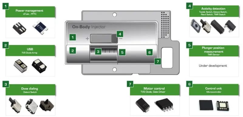
Figure 2: Example of a wearable medical syringe and recommended protection and control components
1.Description of wearable medical syringe
Figure 2 shows a wearable medical syringe. The syringe is shown around the illustration showing the components that provide protection and effective control of the syringe circuitry. Figure 3 shows a block diagram of a wearable medical syringe. The table to the right of the block diagram lists the protection and control components recommended for use in a particular circuit module.
Long-life lithium-ion (Li-ion) batteries power medical syringes. The battery is charged using a USB power supply. Depending on the power requirements of the syringe, the battery is charged using the USB-A, USB-B or USB-C ports, with the USB-A and USB-B ports providing 20 W of charging power and the USB-C port providing 100 W of charging power.
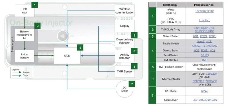
Figure 3: Block diagram of wearable medical syringe
The microcontroller unit (MCU) drives the motor of the syringe and obtains positioning feedback based on activity status detection and position sensors. The injector transmits data through a wireless communication interface and receives modified settings from the medical staff.
2.Stable protection function
Stable operation of equipment requires protection against electrical hazards. The use of specialised components prevents hazards and protects the circuit module. If a USB-A or USB-B interface is used, a polymer positive temperature coefficient (PPTC) resettable fuse provides overcurrent protection for the USB input circuit. Select PPTC fuses with very low resistance to minimise power loss from current flow through the fuse. The internal resistance of PPTC fuses is less than 1Ω for most current ratings, and PPTC fuses are available in small, space-saving surface mount packages.
For higher power USB-C interfaces, a more comprehensive USB input circuit protection alternative is available. This is a single-chip solution, a four-side-pin surface-mount integrated circuit that combines overcurrent, overvoltage, and thermal fault protection. Figure 4 illustrates a block diagram of this component, which is part of the Littelfuse eFuse™ family of electronic fuse protection integrated circuits. In addition to overcurrent, overvoltage and thermal fault protection, the eFuse features soft-start circuitry to minimise inrush currents and an undervoltage lockout feature that prevents operation until the supply voltage reaches an appropriate level. To minimise power loss, the electronic fuse uses a series load switching FET with very low on-resistance (26 mΩ), which reduces the input voltage to a level that shuts down the injector as soon as any fault condition is detected. This electronic fuse is packaged in a DFN1.2×1.6_4L surface-mount package, which helps to save space.
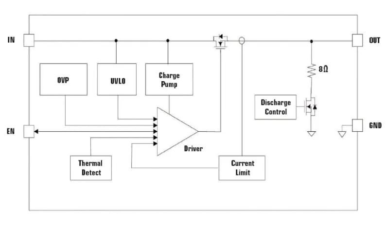
Figure 4: Low Energy Electronic Fuse (Model: LS0504EDD12; 5.5V, 4A)
Battery management integrated circuits monitor the state of charge (SoC) and state of health (SoH) of the battery to maximise battery life. Electrostatic discharge protection is necessary to guarantee stable circuit operation. The Transient Voltage Suppressor (TVS) bi-directional diode array contains two TVS diodes connected anode-to-anode to safely absorb ESD shocks up to ±30 kV. This model of TVS diode achieves a nanosecond response and clamps the voltage to 10 V to safeguard the stable operation of the battery integrated circuit.
Motor drive circuits need to be protected against power surges and electrostatic discharges, and TVS diodes protect the circuits from both hazards. Available surface mount assemblies can safely absorb up to 400 W of surge pulse power and 30 kV of ESD impact. These TVS diodes have a very fast transient response of less than 1 ps. Two configurations are available, a unidirectional single diode design and a bidirectional cathode-to-cathode device.
TVS diodes also have the function of protecting the display and preventing electrostatic discharge in wireless communication circuits. Low capacitance TVS diodes minimise distortion of low level RF signals and avoid errors when receiving signals. Only a few components are required to protect circuits from electrical hazards. These components consume very little energy and are available in surface mount packages for effective space saving.
3.Constantly optimised for efficient sensing and control functions
Minimising energy consumption and saving space requires efficient, small sensing and control circuit modules. Designers can use the following methods to achieve these two design goals.
Dose delivery detection circuits require switches to indicate the position of the vial. Surface-mount detection switches are available in 3.5 mm wide x 2.8 mm deep x 3.35 mm high, with actuation forces as low as 35 g. The switches have a contact resistance as low as 500 mΩ and a service life of over 100,000 cycles. Contact resistance is as low as 500 mΩ and service life exceeds 100,000 cycles. Designers can choose top or side activation.
The active state detection circuit has a variety of functions, including drug vial safety indication and verification that the syringe output current is contacting the patient’s skin. The circuit also activates drug injection and performs drug dosage monitoring. Designers can detect these states in several ways.
The first method of activation is a small, discreet, top-operated, surface-mounted push-to-talk switch. The dimensions are 2.5 mm wide x 1.65 mm deep x 0.55 mm high.The switch is rated IP67 for moisture and dust protection. The service life can be up to 300,000 cycles with a contact resistance as low as 500 mΩ. The second type is a detection switch, which detects the infused dose by means of a circuit.
The third type is the reed switch. Designers can use ultra-compact hermetically sealed reed switches with variable sensitivity. The magnetic actuation does not consume power in the circuit, and the leakage current of the switch is so insignificant that it can be measured only in pico-amps.
The fourth option is a tunneling magnetoresistive (TMR) switch. It consists of a magnetic tunnel junction sensor and CMOS circuitry. This magnetically triggered digital switch combines high sensitivity and ultra-low power consumption. Figure 5 shows the block diagram of the tunneling magnetoresistive switch. A temperature-compensated voltage regulator circuit ensures voltage stability in the internal circuit. The Schmitt trigger has a switching hysteresis characteristic that suppresses noise. a CMOS push-pull circuit provides the output drive.
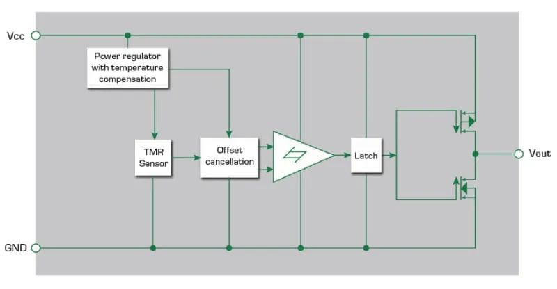
Figure 5: Integrated switch containing tunnelling magnetoresistive sensor and driver circuitry
The tunnelling magnetoresistive switch is located at one end of the bottom of the syringe plunger chamber and has a small magnet mounted on the syringe plunger. As the motor pushes the plunger against the bottom of the syringe and tunnelling the reluctance switch, the switch generates an increasing output voltage and switches the logic state. The switch indicates the position of the plunger. The microcontroller (MCU) uses the position information to determine the volume of injected drug.
The Tunneling Magnetoresistive Switch consumes only 200 nA of current when powered by a 1.8V-5V circuit and can detect magnetic fields as low as 5 gauss. the CMOS output can be connected directly to the MCU without the use of additional components. The high sensitivity and low power consumption minimises battery power consumption, making the Tunneling Magnetoresistive Switch the optimal solution for drug dosage monitoring in wearable syringes.
The injector is controlled using a microprocessor or microcontroller. A single-chip MCU provides all the required functionality and consumes less energy, favouring savings in storage space and energy consumption.The sleep mode of the MCU significantly reduces energy consumption during inactivity.
Highly efficient 8-bit MCUs can be used to control syringe operation. The available MCUs operate with currents as low as 2 mA. slowing down the pulse rate setting further reduces the operating current. These MCUs are configured with a low-energy inactive state mode with current consumption as low as 0.7 μA. These models can be equipped with 15 ADC analogue-to-digital channels with 12-bit resolution, 16 kb of flash memory, and an on-chip array of temperature sensors. In addition, these MCUs are configured with high-resolution timers for PWM-driven motors.
The MCU is also configured with peripheral I/O ports optimised for connection to wireless communication chipsets. For effective motor control, a gate driver can be used to connect the MCU to the motor driver of the power module MOSFET or IGBT. The gate driver is configured with TTL and CMOS circuit inputs that can be connected directly to the MCU output control lines. The use of one logic input type, the Schmitt trigger, minimises motor torque ripple and has a 50 ns propagation delay between the high and low side outputs, enabling precise control of the motor.
4.Standards for wearable medical syringes
Medical devices are heavily regulated to ensure patient safety. Table 1 shows the common global standards that product design engineers must adhere to when developing compliant devices. Knowledge of these standards and their impact on device design is critical to obtaining regulatory approval for medical devices.
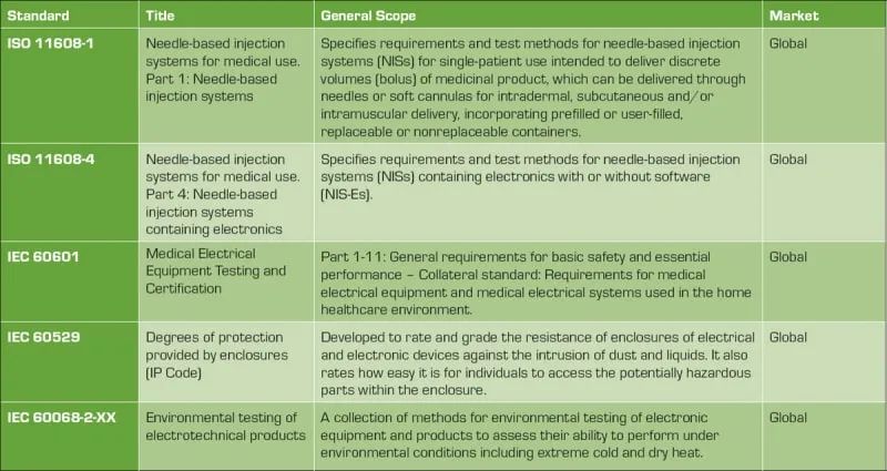
Table 1: Applicable standards for wearable medical syringes
5.Stable and efficient professional design
Wearable medical syringes must remain operational 24 hours a day, 7 days a week. Therefore, it is critical to ensure stable and reliable performance. Syringes should not be subject to overcurrent, overvoltage, overheating, or electrostatic discharge. Adding power supply protection components can meet the requirements of small device size, low energy consumption and light weight. The surface mount low energy components presented in this paper minimise the disadvantages to the circuitry and do not have a significant impact on size, energy consumption and weight.
Designers can save development time and compliance costs by leveraging the expertise of component manufacturers. Product application engineers can help designers select cost-effective protection and control components, as well as provide guidance on design requirements as defined by applicable standards. To save testing costs and avoid delays in product delivery due to multiple compliance tests, some manufacturers can perform pre-compliance testing in case of test failure. With the assistance of experts, and in combination with the application of recommended components, it is possible to manufacture wearable medical syringes that are low in energy consumption, robust, small in size and light in weight.


