
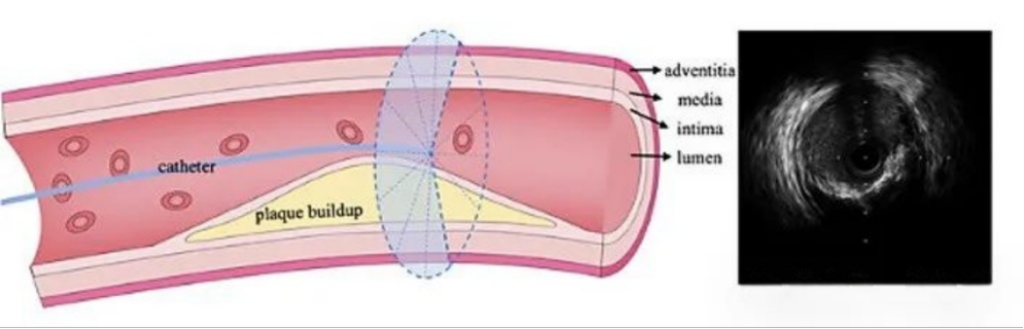
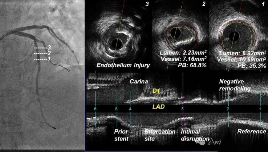
What is IVUS ultrasound? Intravascular ultrasound (IVUS) is an interventional imaging technique that uses a specially designed imaging catheter with a miniature ultrasound probe at the distal end and a host computer at the proximal end. The technique uses a specially designed imaging catheter with a miniature ultrasound probe at the distal end and an ultrasound host at the proximal end. The miniature ultrasound probe is placed into the lumen of the blood vessel through the imaging catheter to obtain precise images of the structure of the blood vessel wall and lumen shape in real time. Coronary arteries are the most common imaging target for IVUS. When atherosclerosis develops in the arterial wall, decades of evolution can result in the formation of unstable, vulnerable plaque, the dislodgement of which can lead to blood clots that can cause a stroke or heart attack, and IVUS is able to quantify the volume of plaque within the arterial wall and/or the degree of luminal narrowing, which is important especially when angiographic results are unreliable (e.g., insufficiently visible lumen of an open lesion, or areas where overlapping vessels cause blurred images). areas that result in blurred imaging) is of great value. In addition, IVUS can be used to assess the efficacy of stenosis treatment (e.g., the efficacy of balloon dilatation, stenting) and the long-term results of pharmacologic therapy.
Difficulty 1: Structural Design of IVUS Imaging Catheters
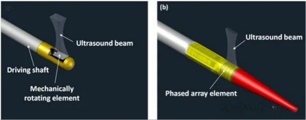
There are two basic design types for IVUS imaging catheters: single-array rotary scanning and phased-array electronic scanning. When designing IVUS imaging catheters, it is first necessary to clarify the application scenarios. For example, if applied to coronary vessels, the mechanical rotary structure is prioritized, whereas if applied to peripheral vasculature, the phased-array electronic scanning structure can be considered. Single-array rotary scanning imaging catheters consist of a single-array transducer mounted on the front end of a torque spring, which is placed in a protective tube and manipulated for rotational scanning by an external retraction control device. This type of imaging catheter produces IVUS images with guidewire artifacts present all the time due to the guidewire being parallel to the ultrasound transducer outside the ultrasound transducer, causing a certain angular deficit for vascular detection, and this type of imaging catheter is generally smaller in diameter with better pass-through properties. In contrast, phased-array electronically scanned imaging catheters do not contain rotating parts, and have a peripherally arranged transducer array, which is sequentially activated with different time delays to produce ultrasound beams scanning along the circumferential direction of the vessel. This type of imaging catheter is safer to apply and avoids non-uniform rotational distortion artifacts, while its guidewire is inside the ultrasound detector, which avoids guidewire artifacts.
Difficulty 2: Miniaturization of Ultrasound Transducers
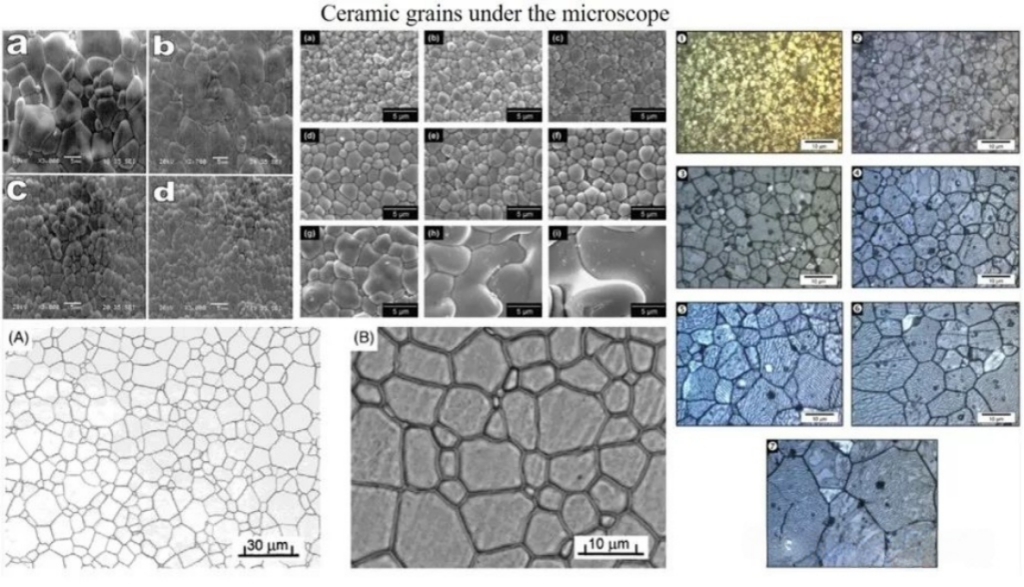
In order to assemble the ultrasound transducer at the front end of the imaging catheter, the transducer needs to be made small enough, typically several hundred microns in size. Piezoelectric ceramics are commonly used for IVUS transducers. The grain size of the ceramics is usually unevenly distributed, ranging from a few micrometers to tens of micrometers, which is very close to the target thickness of the piezoelectric material. When the ceramic is thinned to a specified thickness by a milling process, the mechanical strength of the material decreases dramatically as the thickness approaches the grain size, resulting in material embrittlement. At this point the material may flake off in the form of grains, resulting in a deterioration of the material homogeneity. Not only do the piezoelectric properties of the materials obtained in this way deteriorate dramatically, but their performance parameters may even become unpredictable – a drawback that makes ceramic materials unsuitable for the fabrication of ultrahigh-frequency devices.
Single-crystal materials with extremely high piezoelectric constant d33 and electromechanical coupling coefficient kt are ideal for the preparation of high-performance transducers. Unlike ceramics, single crystals are not limited by grain size and porosity, and have the potential to fabricate UHF transducers. The large-sized single crystals obtained from growth usually need to be cut into wafers, and since single crystals have crystallographic axes, the cutting direction will directly affect their piezoelectric properties – different device performance requirements correspond to different cutting methods: the cut of the crystal surface perpendicular to the x-axis of the crystal is known as the x-cut, and the other axial cuts are the same. The preparation of high-frequency ultrasonic transducers based on single crystals requires a lot of time and effort, and the difficulty of the process may increase non-linearly as the center frequency is further increased.
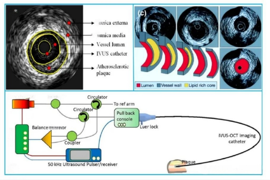
Difficulty 3: IVUS probe packaging
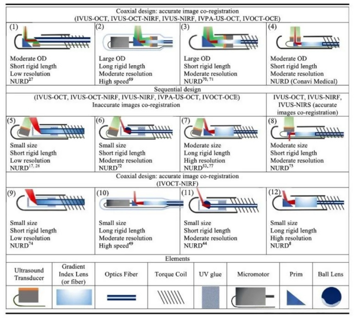
There are two forms of IVUS imaging probe encapsulation, the first encapsulation mode structure is characterized by the core wire connected to the surface of the array element and the shield wire connected to the back of the array element (ground or reference electrode), this form of core wire directly transmits high-frequency electrical signals to the surface of the array element, excites the piezoelectric material to produce ultrasound or receive echo signals, with a lower path impedance and high signal efficiency, in addition, through optimization of the process to reduce the surface of the array element and core wire contact area of the array element surface and core wire, which can improve the effective aperture size. Shielded wires are connected to the back side to form a closed loop, while providing electromagnetic shielding to reduce external interference. The structure of the second encapsulation method is characterized by the surface of the array element being connected to the metal protection tube (usually gold-plated), the shielding wire also being connected to the metal protection tube, and the core wire being connected to the back of the array element. The metal protection tube serves as the overall shielding layer, and at the same time provides a uniform ground reference for the surface of the array element to reduce the noise caused by potential difference. It is suitable for phased array multi-array structures to avoid ground loop problems, while this structure can simplify the packaging complexity. However, the direct conduction between the metal tube and the surface of the array element may lead to high-frequency signal loss, and the insulation of the area around the transducer needs to be handled carefully to avoid signal short circuits.
Difficulty 4: Design of the sheath
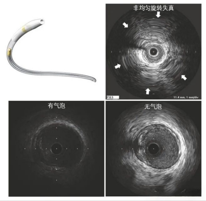
Another important component of the IVUS imaging catheter, the outer sheath that is in direct contact with the vessel, is equally important to design. A good IVUS sheath should balance matching acoustic impedance, support and flexibility, and size and fit to the internal catheter. The sheath usually consists of a support section, an imaging section, and a guidewire sheath, with the imaging section being the imaging window through which the ultrasound signal penetrates into the vascular tissue, and thus requires good acoustic impedance matching. In general, the softer the tissue, the weaker the acoustic attenuation, however, the poorer the support, so you need to choose a balance of support and acoustic impedance of the material, common choices are Pebax, PE, LDPE, and can be changed by changing the ratio of the components of the material or reference to other materials to achieve better performance, such as reference to polypropylene materials. The reason why it is necessary to consider whether the size and dimensions of the sheath matches the internal catheter is that the IVUS imaging catheter may have air bubbles during operation, resulting in a serious degradation of image quality, which is usually improved by pumping water through a syringe at the back end of the outer sheath. When the size of the outer sheath tube does not match the size of the inner catheter, this can result in the appearance of air bubbles that occur frequently and are not well ameliorated, and in addition, the mismatch may exacerbate non-uniform rotational distortion of the image. In general, the inner diameter of the outer sheath tube can be selected to be about 0.1 mm larger than the outer diameter of the inner catheter, and the above situation can be better improved by coating the inner wall of the outer sheath tube with a hydrophilic film.
Overall, IVUS imaging catheter assembly challenges include the design of the transducer structure, miniaturized fabrication of the high-performance transducer, encapsulation of the probe, and the design and fabrication of the sheath. The development of high-quality IVUS imaging catheters requires extensive engineering and validation. Although today’s development trend of IVUS is not limited to the enhancement of engineering technology of IVUS itself, such as the integration of multi-frequency single-array transducers, the integration of other modalities (e.g., optical coherence chromatography, photoacoustic, fluorescence, etc.), the application of super-surfaces, and new piezoelectric materials, etc., the finalization of a variety of complex structure and morphology of IVUS-based imaging catheters still depends on the precision assembly process and the manufacturing of sheath tubes, no matter how much the technology has evolved. The finalization of various IVUS-based imaging catheters with complex structures and different morphologies still depends on the precision assembly process and strict engineering validation.